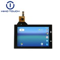
tft lcd display
After the etching mask printing process, is etched on the substrate surface 11 is performed, followed by peeling of the membrane (Stripping) is executed. Thus, a transparent and conductive properties, a first axial conductive cell 131 of the first axial conductor component assembly 13, a first axial conductive wire 132, a second axial conductor of the second axial conductive component assembly 14 and the cell 141 (as shown in FIG. 7) is formed on the substrate surface 11. At this time, all of the first axial conductor cells 131 of the same first axial conductive component assembly 13 is electrically connected together, and, in a first axial conductive component assembly 13 are a plurality of signal transmission lines 16a It is further connected.
Thereafter, as shown in Figure 8, the insulating layer 17 is applied to cover the conductive line surface 133 of the first axial conductive wire 132. Next, a mask is formed to define the position of the second axial conductive wire 142 using a printing technique. Subsequently, a second axial conductive wire 142 formed by coating the transparent conductive layer, as shown in FIG. 9, the second axial conductive cells 141 which are adjacent to each other along the second axis Y and a second axial are connected to each other by conductive wires 142, each of the second axial conductive wire 142 extends across the surface of the insulating layer 17. After completing the above steps, all the second axial conductive cells 141 of the same second axial conductive component assembly 14 is electrically connected together, a second axial conductive component assembly 14 is a signal transmission line 16b It is connected to.

When employed the above-described etching method to form a conductive cell and the conductive line on the surface of the substrate, in order to similarly configured conductive pattern structure, by etching the area defined by different etch mask to etch different patterns be able to. For example, in steps of one-time etching, but only the first axial conductive cell 131 and the first axial conductive wire 132 of the first axial conductor component assembly 13 is formed on the substrate surface 11, where the second axial conductive cell 141 2 axial conductive component assembly 14 is not formed. Then, the same etching method is employed again, the insulating layer in which the second axial conductor cells 141 and the second axial conductive wire 142 is formed on the substrate surface 11, the second axial conductive wire 142 corresponding extending across the surface of 17.
In the above-described embodiment, the first axial conductive cell and the second axial conductive cell, are formed on a substrate in the form of a plurality of component assembly, constituting a conductive pattern structure of a capacitive touch panel. Based on the same creation spirit, is also available a small number of conductive cells, it is possible to constitute a conductive pattern structure of a capacitive touch panel.

Figure 10 is a conductive pattern structure of a capacitive touch panel of the present invention, it is a plan view of a second embodiment. In this embodiment, the first axial conductive cell 31, 32 of two adjacent is formed on the substrate surface 21 of the substrate 2, the signal transmission line 34 is connected to the first axial conductive cell 32. The first axial conductive wire 33 connects the first axial conductive cell 31, 32 adjacent thereto. Insulating layer 4 is formed on the surface of the first axial conductive wire 33.
The first axial conductive cell 31, 32 along the different axial, second axial conductive cell 51, 52 of two adjacent is placed. Second axial conductive wire 53, by extending across the surface of the insulating layer 4, which connects the second axial conductive cell 51, 52 adjacent thereto. The second axial conductive cell 52 also connected to the signal transmission line 54.
Email: sales08@wiwotouch.com
Our team will reply you as soon as possible
Tel:0086-596-2607595
call us with any questions
Have a nice day
Thankyou for your time
Hot Tags: tft lab test, China, suppliers, manufacturers, factory, best, price, MDT Taxi Management, 7inch Touch Screen Panel Capacitive, Circular 7inch Capacitive Touch Screen Products, China 12 Panel PC, Capacitive Touch Screen Tablet Android, Hdmi Capacitive Touch Screen


